Implementation of the Corroded Tension Chord Model as User Programmable Feature in ANSYS Mechanical APDL
Author: Fabian Hirzel
Language: English
Abstract
The Corroded Tension Chord Model describes the altered load-deformation behaviour of a locally corroded crack element by capturing the strain localisation at the corrosion pit. In the corroded section of the crack element, no bond shear stresses are considered to be transferred between reinforcement and the concrete, and thus, no tension stiffening occurs in this section. The loss of cross-sectional area leads to higher steel stresses and strains in the corroded section, compared to an adjacent section. As a result, the load-bearing and deformation capacity decrease significantly. The reduced deformation capacity is especially critical for statically indeterminate reinforced concrete structures, as well as those with deformation-dependent loading, since in both cases a sufficient deformation capacity is assumed.
To determine the residual deformation capacity and the corresponding ultimate load of existing locally corroded reinforced concrete structures, the Corroded Tension Chord Model is implemented in a finite element analysis software. An existing custom material model in ANSYS Mechanical APDL, the CMM Usermat, describes the non-linear behaviour of reinforced concrete elements based on the Cracked Membrane Model and provides a good basis for the analysis of locally corroded elements. Within the scope of this Master’s Thesis, the CMM Usermat is extended by the Corroded Tension Chord Model.
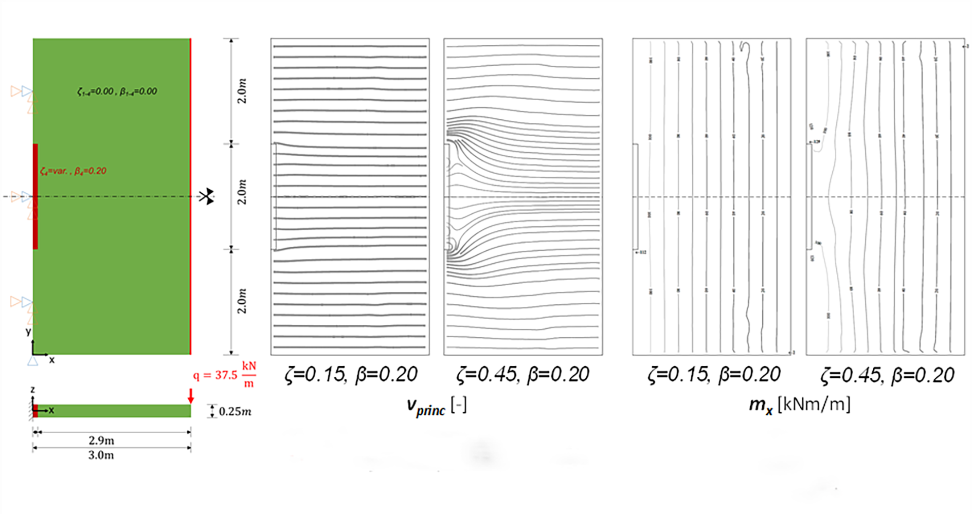
After verifying the results of the extended CMM Usermat on membrane elements loaded in plane, the plausibility of the results is checked by using the example of a locally corroded cantilever slab, for which the influence of different corrosion situations on the load-deformation behaviour are investigated. As shown in Figure 1, the principal tensile reinforcement at the fixed support of the cantilever slab is affected by local corrosion in the middle of the supported length (dark red). The results clearly show that the load redistribution from the inner, corroded region to the outer, stiffer region of the cantilever slab increases for larger cross-section losses. This is apparent in the direction of the principal shear force vprinc and in the distribution of the internal moment mx, plotted in Figure 1 for a cross-sectional loss of ζ=0.15 and ζ=0.45. Overall, the results coincide with the expectations and are plausible.
The extended CMM Usermat is a valuable numerical tool to investigate the influence of local corrosion on the load-carrying and deformation capacity of affected structures, as e.g., cantilever retaining walls and bridge decks, to analyse their altered load-carrying behaviour, and estimate their risk of failure.